
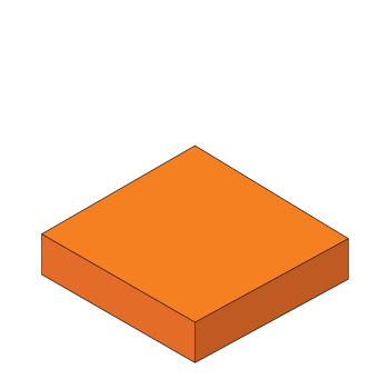
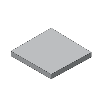
Typical Assembly:
Top Sliding Plate:
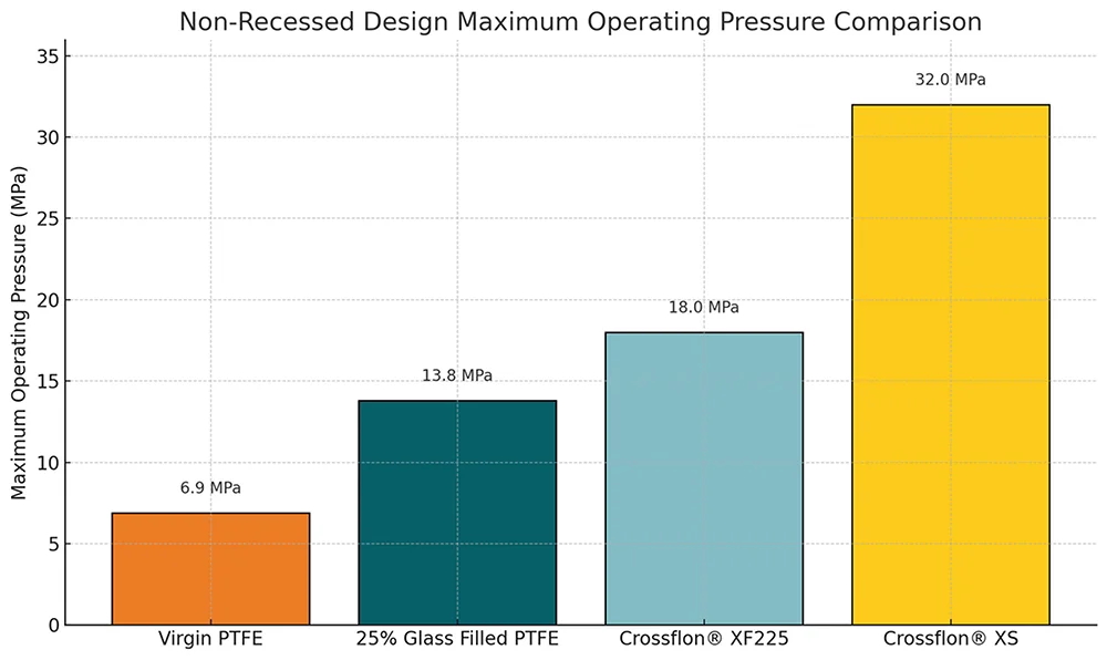
2.5mm thick Crossflon® XF225 bonded to a 3mm thick carbon / stainless steel plate.
Bottom Sliding Plate:
2.5mm thick Crossflon® XF225 bonded to a 3mm thick carbon / stainless steel plate.
Method of Installation:
Tack welding, full welding, bolting.
2.5mm thick Crossflon® XF225 bonded to a 3mm thick carbon / stainless steel plate.
Bottom Sliding Plate:
2.5mm thick Crossflon® XF225 bonded to a 3mm thick carbon / stainless steel plate.
Method of Installation:
Tack welding, full welding, bolting.
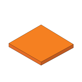
- Carbon / stainless steel
- Crossflon® XF225
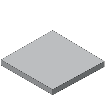
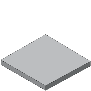
Typical Assembly:
Top Sliding Plate: 3mm thick polished stainless steel plate.
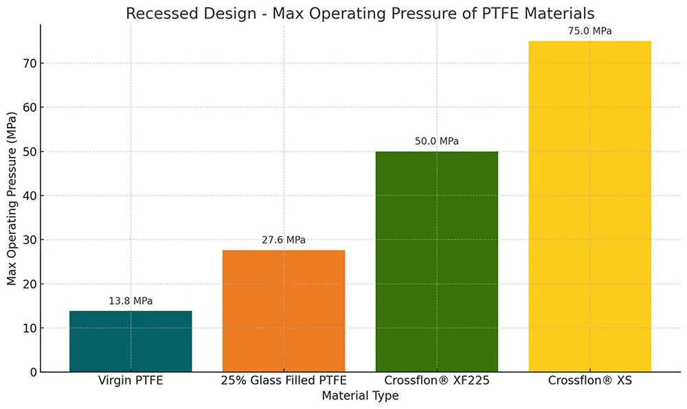
Bottom Sliding Plate: 5mm thick Crossflon® XF225 bonded into a 2.5mm deep recess in an 8mm thick carbon / stainless steel plate.
Method of Installation: Tack welding, full welding, bolting, mortar embedment.
Top Sliding Plate: 3mm thick polished stainless steel plate.
Bottom Sliding Plate: 5mm thick Crossflon® XF225 bonded into a 2.5mm deep recess in an 8mm thick carbon / stainless steel plate.
Method of Installation: Tack welding, full welding, bolting, mortar embedment.
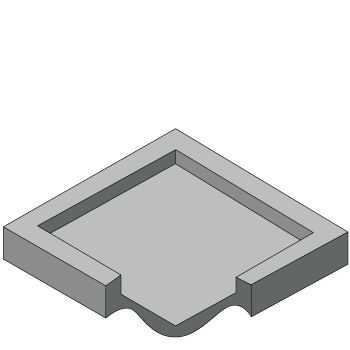
- Polished stainless steel
- Crossflon® XF225
- Carbon / stainless steel
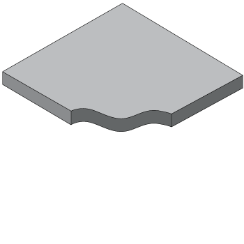
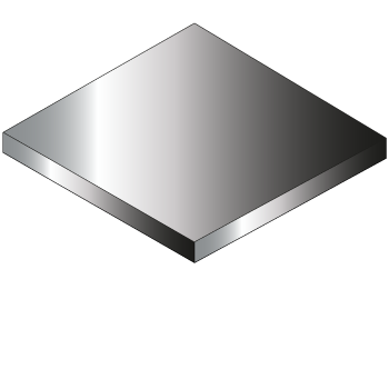
Typical Assembly:
Top Sliding Plate: 2.5mm thick Crossflon® XF225 bonded to a 3mm thick carbon / stainless steel plate. Bottom Sliding Plate: 2.5mm thick Crossflon® XF225 bonded to a 3mm thick carbon / stainless steel plate bonded to a 6mm thick elastomer sheet bonded to a 3mm thick carbon / stainless steel plate.
Method of Installation:
Tack welding, full welding, bolting, mortar embedment.

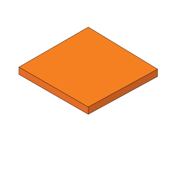
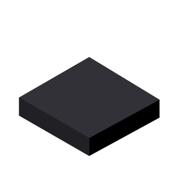
- Carbon / stainless steel
- Crossflon® XF225
- Elastomer
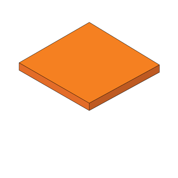
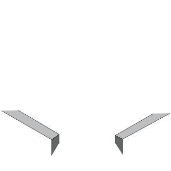
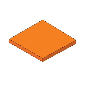
Typical Assembly: Top Sliding Plate: 3mm thick polished stainless steel plate. Bottom Sliding Plate: 5mm thick Crossflon® XF225 bonded into a 2.5mm deep recess in an 8mm thick carbon / stainless steel plate. Method of Installation: Tack welding, full welding, bolting, mortar embedment.
- Polished stainless steel
- Crossflon® XF225
- Carbon / stainless steel
")